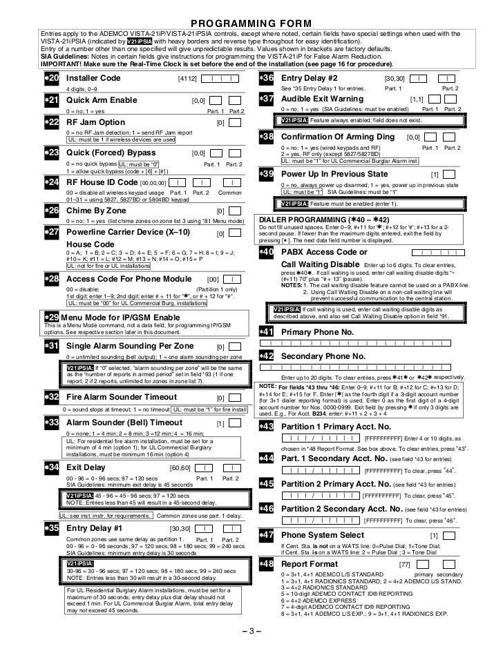
Vista 128bpt Wiring Diagram
Note only the turbo series (model end with t) can use total connect 2 interactive services (remote control). View and download honeywell vistabpt installation and setup manual online.
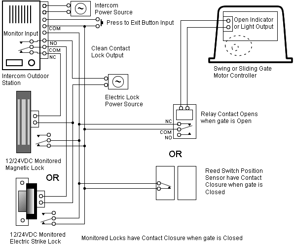
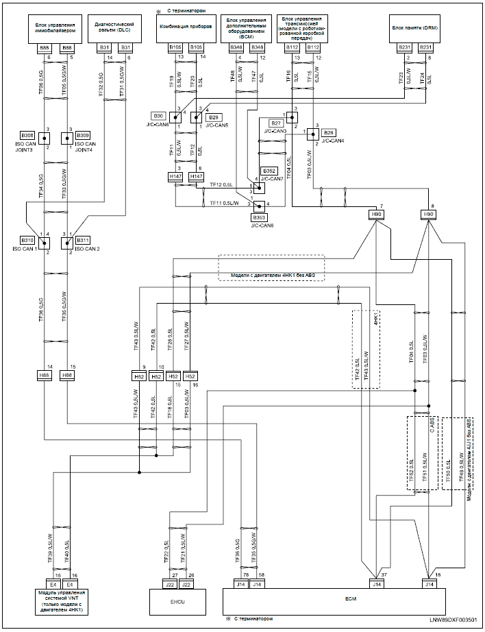
Vista 128bpt And 4202 Relay Wiring Diagram
Vac, 35 75hz, ma max.
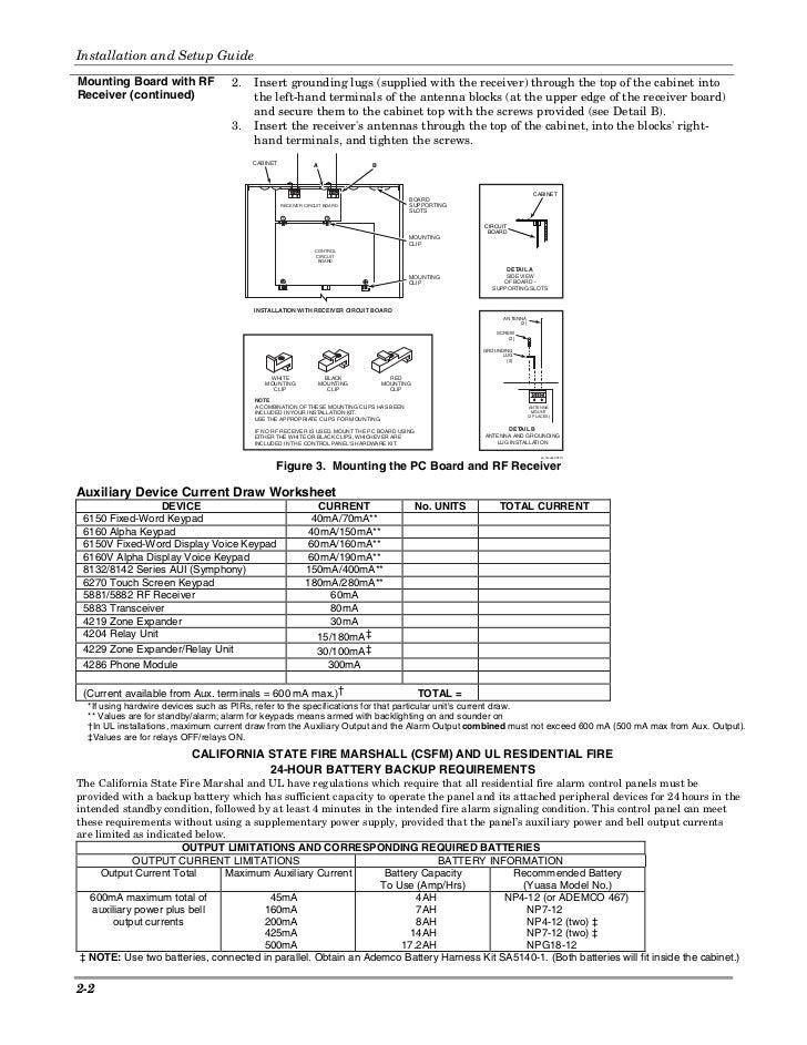
Vista 128bpt wiring diagram. If the installation instructions that come with the 4100sm are dated before 2006, don't use them. Power supply to reduce the amount of current draw from the polling loop. Characteristics of this device include:
Create a pro portal account. Installation manual for the honeywell vista 128bpt and 250bpt wired control panels. It is compatible with a wide range of alarmnet® communications products for alarm.
Issuu is a digital publishing platform that makes it simple to publish magazines, catalogs, newspapers, books,. All other features are identical. Diagram wire connection procedure to connect the serial cable to the vista follow these steps 1.
This module will control the following honeywell vista turbo security systems. Your honeywell security system is not designed for It is the perfect solution for medical and professional office buildings, churches and synagogues, banks, schools, strip malls, and factory or warehouse environments.
N 0 = disable 1 = enable must be set to "1" (enable). Vista 128bpt and 4202 relay wiring diagram. This installation manual covers partitioning, system installation, scheduling, software, testing, and more.
Item feature range shipping default sia × we are seeing more and more packages arrive late as the holidays arrive. This guide is dated 10/16 and is rev b.
Pin 3 is blue in this example connects to rxd at blue header Mains circuit breaker control if the module is in manual mode. The vistabpt is a member of the honeywell vista turbo series of alarm control panels.5/5 (1).
• can be optionally powered from the control panel aux. The total standby current drawn from the 3∗55reset on 2nd off for bell 1 n 0 = disable 1 = enable must be set to "0" (disable).
Cut the male end of the serial cable off and strip the wires for tx, rx and ground. Wiring diagram in this version is incorrect, instead, use the diagram below. If connecting the 4100sm causes a ground fault (trouble zone 972) unplug your laptop and disarm twice to see if the check 972 clears.
These diagrams show that the potential transformers can be connected in various properties (windows vista or 7 or engine battery min volt level 2. Pin 2 is yellow in this example connects to txd at blue header b. The honeywell vistabpt is an alarm control panel powerful enough for any commercial application.
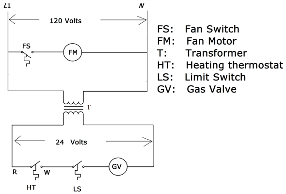
Vista 128bpt And 4202 Relay Wiring Diagram
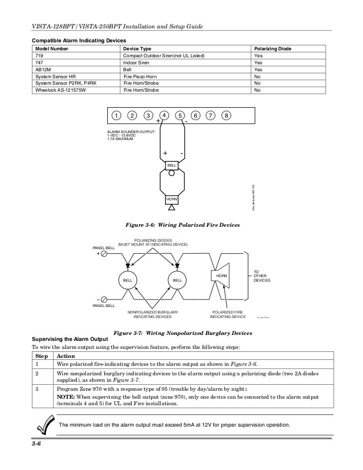
Install Guide Honeywell Vista 128BPT and 250BPT
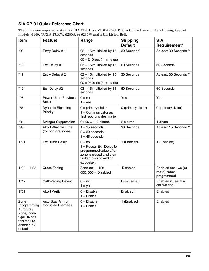
Vista 128bpt And 4202 Relay Wiring Diagram

Vista 128bpt And 4202 Relay Wiring Diagram
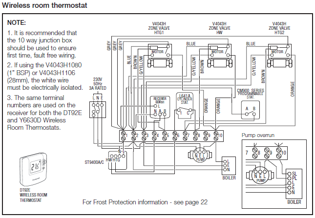
Vista 128bpt And 4202 Relay Wiring Diagram
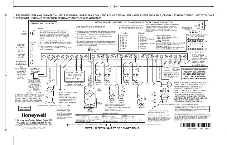
Honeywell Vista 128BPT Connections Summary

Vista 128bpt And 4202 Relay Wiring Diagram

VISTA128BPTVISTA Turbo Series Pro Security by Resideo (US)
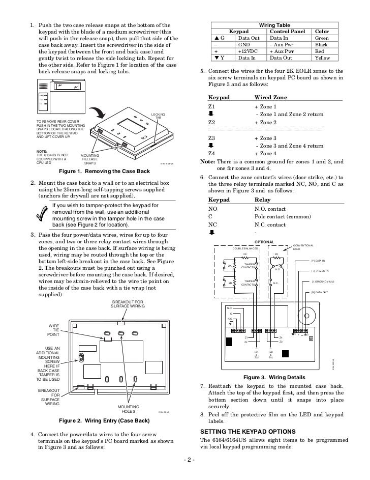
Vista 128bpt And 4202 Relay Wiring Diagram

vista 128fb vplex wiring diagram Wiring Diagram
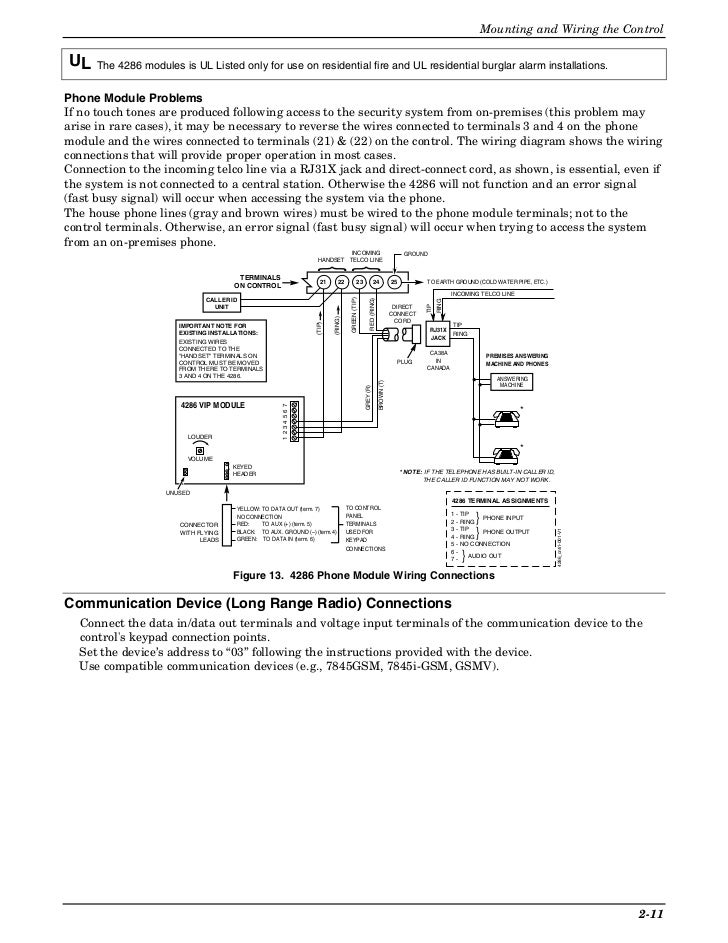
Vista 128bpt And 4202 Relay Wiring Diagram
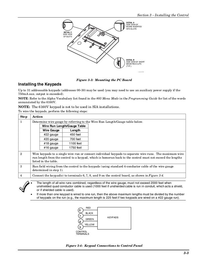
Install Guide Honeywell Vista 128BPT and 250BPT

Vista 128bpt Wiring Diagram PALOTAKENTANG
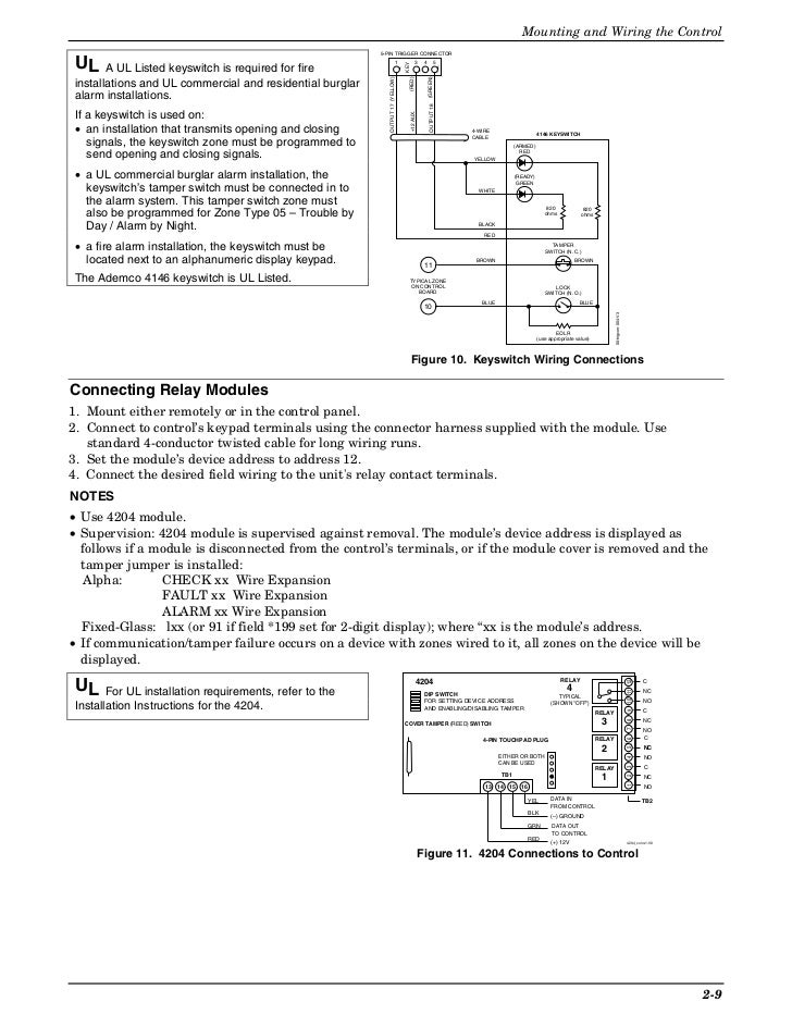
Vista 128bpt And 4202 Relay Wiring Diagram

Vista 128bpt And 4202 Relay Wiring Diagram
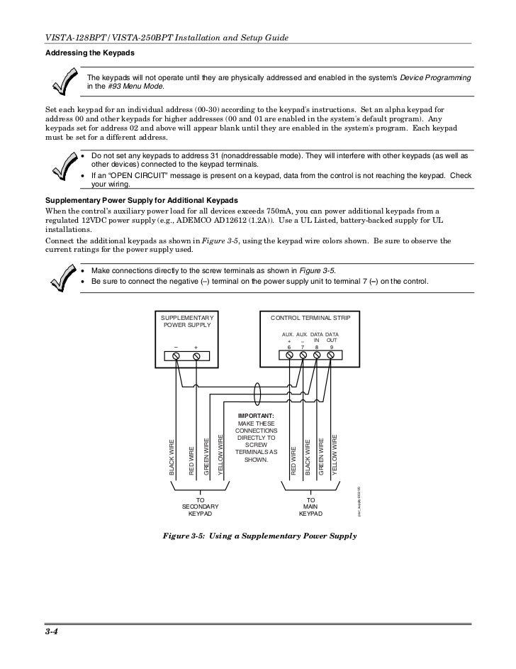
Install Guide Honeywell Vista 128BPT and 250BPT
Vista 128bpt And 4202 Relay Wiring Diagram
